JP Technology Initiatives Inc.

A design that add Foottroller functions to regular shoes, which allow a user to use Foottroller function without changing his/her shoes.
Parts and features:
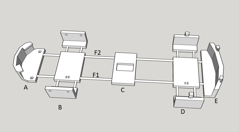
Section A: Provide support for front tip part of the foot, and used as the front anchor of the system.
Section E: Provide support for the heel part of the foot, and used as a heel anchor of the system.
F2 , and F1 are flexible strings/bands that connect (or non-flexible strings with adjustable length) Section A and E, which adapt to different shoe lengths.
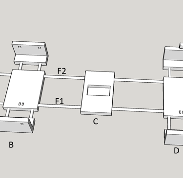
Sections B and D host buttons for foot touch state sensing.
Section C has the IMU sensor for foot tilt angle and foot pointing direction evaluation.
The locations of sections B, C and D can be adjusted (by sliding over F1 and F2), to make sure they are well positioned for getting the measurements.
Section B has two wing parts and a center piece. The center piece has the button installed at the bottom side. The center part and the two wing pieces are connected by flexible strings or bands to make the section's width adjustable according to the user's shoe width. The two wings has holes which are used to attach strings or adjustable bands that help fixing it on the user's shoe.
Section D is similar to Section B, which also hosts a button and has two wings for adjustable width.
Section D and Section E may have hooks attached to the sections using flexible strings/bands or adjustable strings/bands. The hooks help secure the sections on the user's shoes. The hooks can also be replace by bands or strings that tie on the user's shoe or ankles to help secure sections D and E in place.
Contact
email:
support@jptiinc.com
© 2025 JP Technology Initiatives Inc. All rights reserved.
address:
JP Technology Initiatives Inc.
45 Colvin Ave, Suite 120
Albany NY 12206 USA